Texture mapping, part 2
This is intended to be a sequel to the article on texture mapping that Boreal wrote for Hugi 23. Boreal's article is on what is usually called "affine" texture mapping: that is, one picks the texture map, passes it through an "affine" transformation, and draws the result.
What is an "affine" transformation? Simply put, that means that you stretch the texture map after perspective projection has took place: if (u,v) are the coordinates in texture space, and (x,y) are the coordinates in screen space, the formula is simply (u,v) = A (x,y) where A is an appropriate matrix. Computing the matrix is what the precomputation phase in Boreal's code does.
This method is extremely fast, because you only have to do two adds per pixel. Unfortunately, it causes severe distortion in the texture if the z varies a lot between different edges of the texture; this is because the algorithm basically throws away the z coordinate and thus can be exact only if the z coordinate is constant throughout the polygon.
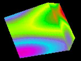
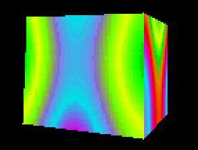
The method I present here is quite the opposite: setting up the algorithm for each polygon is quite expensive, and you have to do two divides (!) per pixel, but the result is perspectively perfect. The two cubes below (in particular, the rightmost faces) can show you the difference:
It is rare to see tutorials with a full derivation of perfect texture mapping; in fact, I could not say to understand it fully before finishing this article. I will first present an even more expensive algorithm that works like this:
1) map the coordinates in screenspace back to 3D space
2) compute an affine transform on the 3D x and y coordinates (rather than on the screen x and y)
3) use the resulting coordinates as offsets in the texture map
I will attack the first two points (the third has nothing special in it); then I'll show a way to reduce the algorithm to the promised two divides per pixel.
Mapping the coordinates in screenspace back to 3D space
First of all, let's clarify a fundamental point. Why is this necessary? Couldn't we do everything in 3D space first, and then everything in screenspace? The answer of course is no, and this is quite a general fact: for example, when doing z-buffering you can fill the buffer only once you know which parts of the buffer are to be filled -- that is, you can compute the value of z for each pixel only after you have done perspective projection and scanline conversion.
Our purpose can be fulfilled with a little algebra, based on this very
important fact: 1/z values are linear in screenspace -- that is,
1/z values are a linear combination of the bidimensional x
and y coordinates. This is easily proven starting from the
equations of a plane and those of perspective projection (here and
throughout the article, lowercase letters indicate 3D space, and
uppercase letters):
         a x + b y + c z + d = 0
         X = x / z
         Y = y / z
and dividing everything by z:
         a x/z + b y/z + c + d/z = 0
         d * 1/z = -a X - b Y - c
         1/z = -a/d X - b/d Y - c/d
This is a useful little theorem that is of common use. For example, most 3D engines (including the original Quake engine by Abrash and Carmack) actually store 1/z values in their z-buffer.
Note that the coefficients in the plane equation are all known: a, b, and c are simply the components of the face normal, and d is computed when you do backface culling (it is the scalar product of the normal and an arbitrary point of the polygon).
Anyway, now we have three values that are linear in screenspace: screen
X, screen Y and 3D 1/z; actually we don't care
about screen Y because we will render our polygon in horizontal
scanlines. We can reverse the perspective projection and obtain the
three-dimensional x and y for each point on the screen:
         x = X * z = X / (1/z)
         y = Y * z = Y / (1/z)
So the basic algorithm is as this (the zInv variable is
1/z):
    for each polygon
        scan convert it
        for each scanline Y
            X1 = leftmost point to be plotted (inclusive)
            X2 = rightmost point to be plotted (inclusive)
            zInv = -a/d * X - b/d * Y - Z;
            for X = X1 to X2
                x = x1 / zInv
                y = y1 / zInv
                zInv = zInv - a/d
                ... map (x,y) to (u,v)...
                ... plot the (u,v) texel at (X,Y)...
Things to be noted:
1) variable names are case sensitive and follow the same convention as the rest of the document
2) the X and Y screen coordinates must be computed as X=x/z and Y=y/z. If you scale and translate them (for example a common choice in a 640x480 resolution is X=480 x/z + 320, Y=480 y/z + 240) you must compensate for this in your code.
3) most of the coefficients can be computed once per polygon
Now, let's proceed.
Compute an affine transform on the 3D x and y coordinates
Some more math... I will show that the u and v coordinates
can be computed from x and y only -- z is not
necessary. This is very easy; certainly u and v are a
linear combination of x, y and z (almost everything
is a linear combination of x, y and z...), so we
can write these equations
         u = I x + J y + K z + L
         a x + b y + c z + d = 0
and substitute from the plane equation:
         z = -d/c - a/c x - b/c y
         u = I x + J y - d/c -a/c x - b/c y + L
           = (I - a/c) x + (J - b/c) y + (L - d/c)
The same holds for v. This is not needed to implement the
algorithm, but only to justify it. So we have to find six values
A, B, C, D, E, F
such that
         u = A x + B y + C
         v = D x + E y + F
This can be found if we have the (x,y) and (u,v) values
for any three points on the polygon. We can set up a system of three
linear equations and solve it. The formula is scary, about as scary
as the following pseudocode:
    den = -x2*y1 + x3*y1 + x1*y2 - x3*y2 - x1*y3 + x2*y3

    if abs(den) is small then
      don't plot the face, it is perpendicular to the viewer

    den = 1.0 / den
    A = (-u2*y1  + u3*y1  + u1*y2  - u3*y2  - u1*y3  + u2*y3)  * den
    B = ( u2*x1  - u3*x1  - u1*x2  + u3*x2  + u1*x3  - u2*x3)  * den
    C = (-u3*x2*y1 + u2*x3*y1 + u3*x1*y2
           - u1*x3*y2 - u2*x1*y3 + u1*x2*y3) * den
    D = (-v2*y1  + v3*y1  + v1*y2  - v3*y2  - v1*y3  + v2*y3)  * den
    E = ( v2*x1  - v3*x1  - v1*x2  + v3*x2  + v1*x3  - v2*x3)  * den
    F = (-v3*x2*y1 + v2*x3*y1 + v3*x1*y2
           - v1*x3*y2 - v2*x1y3 + v1*x2*y3) * den
(There a few places where to apply the distributive property of multiplication, but that would clutter the pseudocode with parentheses).
Now we can be more specific in our rendering loop:
    for each polygon
        compute A, B, C, D, E, F and other common values
        scan convert it
        for each scanline Y
            X1 = leftmost point to be plotted (inclusive)
            X2 = rightmost point to be plotted (inclusive)
            zInv = -a/d * X - b/d * Y - Z
            for X = X1 to X2
                x = x1 / zInv
                y = y1 / zInv
                zInv = zInv - a/d
                u = A * x + B * y + C
                v = D * x + E * y + F
                ... plot the (u,v) texel at (X,Y)...
That's it. Only, I promised two divides and we still have four multiplications.
Removing the multiplications
Let's operate on u alone, since the same simplifications that one
can do on v are exactly the same. We have
         u = A * X / zInv + B * Y / zInv + C
           = (A * X + B * Y + C * zInv) / zInv
Since for two adjacent pixels X varies by 1 and zInv
varies by -a/d, the numerator varies by A + C * (-a/d).
We can then use the numerators as "magic coordinates" (let's call
them m and n) that are related to (u,v) but
increase linearly in screenspace: they are simply
m = u zInv n = v zInv
Using (m,n) instead of (x,y) we have the final algorithm:
    for each polygon
        compute A, B, C, D, E, F and other common values
        scan convert it
        for each scanline Y
            X1 = leftmost point to be plotted (inclusive)
            X2 = rightmost point to be plotted (inclusive)
            zInv = -a/d * X - b/d * Y - Z
            m = (A * X + B * Y + C) * zInv
            n = (D * X + E * Y + F) * zInv
            dm = A - C * a/d
            dn = D - F * a/d
            for X = X1 to X2
                u = m / zInv
                v = n / zInv
                zInv = zInv - a/d
                m = m + dm
                n = n + dn
                ... plot the (u,v) texel at (X,Y)...
For now, that's it... Next time, I will remove the two divides as well. This is quite tricky because it involves approximation (affine texture mapping being the most brutal of the approximations).
Have fun!
--
|_  _  _ __
|_)(_)| ) ,'
-------- '-._